Remote Control Research
Purpose: The purpose of this project was to learn more about reverse engineering, and how it works. In order to do this, we took apart a remote control and observed the various parts of the interior. We researched these parts and took note of how they worked together, in order to get a better understanding of the control.
Hypothesis: The remote control uses radio waves, joysticks, and triggers to control the car.
Disassembly and Analysis: By unscrewing the back of the control, we could observe the interior. The first thing that stands out are the joysticks. The joysticks function is to create connections by sending currents through a metal plate leading to the breadboard. Depending on the direction they are moved, or pushed down, the connection changes. The next thing to analyze is the breadboard. The different resistors have different resistances which regulate and direct the current. There is a chip as well, which stores information and sends signals to the car. The switch is connected to an LED, and when flipped on lights up the LED, and activates the breadboard. The battery pack is connected to the V- and V+ inputs to send a current. The 7 resistors each contain a different resistance, and the 6 capacitors store different amounts of energy. These both allow proper function in the breadboard. When a joystick is moved or triggers are pressed, it sends an electric current through the chip that processes the action to the car.
Structural Analysis: There are 4 screws holding the backing in. The plastic shell protects the interior of the control. There are 2 outer shells of the control. On the back there is a removable cover for the battery pack. The breadboard is screwed into the front shell. All the components are firmly soldered into the breadboard.
Material Analysis: The chip is the IC:SCTX2B/DIP-14, the board contains 6 capacitors, and their values are 22pF, 101pF, 10pF, 7pF 104pF, and 104pF. There are 7 resistors, with resistances of 24kΩ, 4.6kΩ, 410Ω, 100Ω, 390Ω, 3.3kΩ, and 10Ω. There are 2 inductors, with values of 2.1 and 2.2μH. The transistors are C945 P908; the first two diodes are labeled 41 48 ST. The circuit board is plastic, with printed labels, and there is metal on the back to carry an electrical current through the board. These materials allow the board to have electrical properties. Many of the smaller pieces, like resistors and capacitors, are plastic with metal legs that can be soldered into the board. Soldering is a solid way of attaching smaller parts and keep them intact. The outer shell is a hard, protective plastic that protects the circuit board. Batteries are connected with insulated wires that are soldered in to power the circuit board. This allows the current to pass through easily, and for the board to work correctly. At the top of the circuit board, a metal antenna is attached which helps to send a signal to the car, and make a connection between the two. It’s held together by metal screws.
Manufacturing Analysis: All the plastic used in the remote was likely made using molds, which is a forming method. The separate segments of the antenna were also formed, but they were attached to each other, and the screw at the bottom, which is a joining method. The circuit board was created using a forming method, and joining methods were used when the parts were attached to it. The sticks, being plastic, were also formed using a mold, but were then joined with a screw. Finally, all the parts were joined together using screws to create the final product.
Works Cited
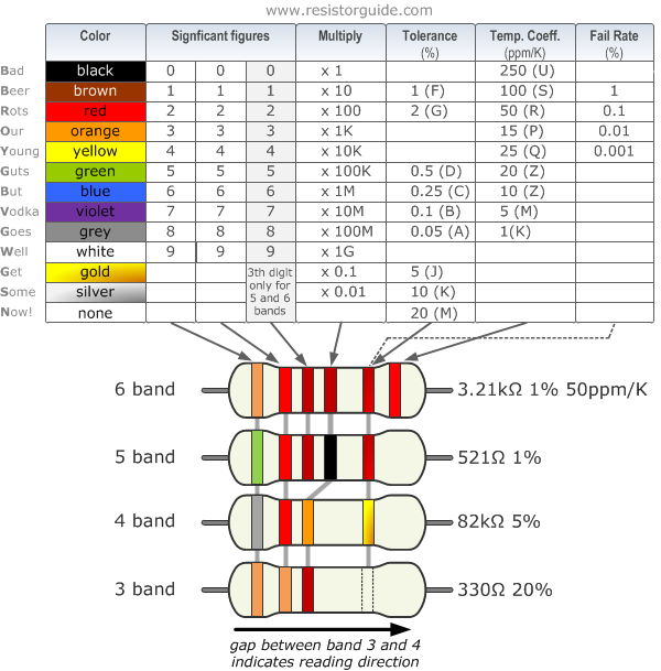
http://www.resistorguide.com/pictures/resistor_color_codes_chart.png
https://electronics.howstuffworks.com/rc-toy.htm
http://www.radioradar.net/en/datasheets_search/S/C/T/SCTX2B_Superchip.pdf.html
https://www.pcbtrain.co.uk/blog/the-basics-of-printed-circuit-boards-design-components-and-construction
http://www.learnabout-electronics.org/ac_theory/inductors04.php
Purpose: The purpose of this project was to learn more about reverse engineering, and how it works. In order to do this, we took apart a remote control and observed the various parts of the interior. We researched these parts and took note of how they worked together, in order to get a better understanding of the control.
Hypothesis: The remote control uses radio waves, joysticks, and triggers to control the car.
Disassembly and Analysis: By unscrewing the back of the control, we could observe the interior. The first thing that stands out are the joysticks. The joysticks function is to create connections by sending currents through a metal plate leading to the breadboard. Depending on the direction they are moved, or pushed down, the connection changes. The next thing to analyze is the breadboard. The different resistors have different resistances which regulate and direct the current. There is a chip as well, which stores information and sends signals to the car. The switch is connected to an LED, and when flipped on lights up the LED, and activates the breadboard. The battery pack is connected to the V- and V+ inputs to send a current. The 7 resistors each contain a different resistance, and the 6 capacitors store different amounts of energy. These both allow proper function in the breadboard. When a joystick is moved or triggers are pressed, it sends an electric current through the chip that processes the action to the car.
Structural Analysis: There are 4 screws holding the backing in. The plastic shell protects the interior of the control. There are 2 outer shells of the control. On the back there is a removable cover for the battery pack. The breadboard is screwed into the front shell. All the components are firmly soldered into the breadboard.
Material Analysis: The chip is the IC:SCTX2B/DIP-14, the board contains 6 capacitors, and their values are 22pF, 101pF, 10pF, 7pF 104pF, and 104pF. There are 7 resistors, with resistances of 24kΩ, 4.6kΩ, 410Ω, 100Ω, 390Ω, 3.3kΩ, and 10Ω. There are 2 inductors, with values of 2.1 and 2.2μH. The transistors are C945 P908; the first two diodes are labeled 41 48 ST. The circuit board is plastic, with printed labels, and there is metal on the back to carry an electrical current through the board. These materials allow the board to have electrical properties. Many of the smaller pieces, like resistors and capacitors, are plastic with metal legs that can be soldered into the board. Soldering is a solid way of attaching smaller parts and keep them intact. The outer shell is a hard, protective plastic that protects the circuit board. Batteries are connected with insulated wires that are soldered in to power the circuit board. This allows the current to pass through easily, and for the board to work correctly. At the top of the circuit board, a metal antenna is attached which helps to send a signal to the car, and make a connection between the two. It’s held together by metal screws.
Manufacturing Analysis: All the plastic used in the remote was likely made using molds, which is a forming method. The separate segments of the antenna were also formed, but they were attached to each other, and the screw at the bottom, which is a joining method. The circuit board was created using a forming method, and joining methods were used when the parts were attached to it. The sticks, being plastic, were also formed using a mold, but were then joined with a screw. Finally, all the parts were joined together using screws to create the final product.
Works Cited
http://www.resistorguide.com/pictures/resistor_color_codes_chart.png
https://electronics.howstuffworks.com/rc-toy.htm
http://www.radioradar.net/en/datasheets_search/S/C/T/SCTX2B_Superchip.pdf.html
https://www.pcbtrain.co.uk/blog/the-basics-of-printed-circuit-boards-design-components-and-construction
http://www.learnabout-electronics.org/ac_theory/inductors04.php
Gantt Chart:
https://docs.google.com/spreadsheets/d/189jt4TNDUUrDGS_8Nwlx5k3m3zKBoBqBu91EKLMLIlM
